CloudZao/MetalioClaw4
GitHub: CloudZao/MetalioClaw4
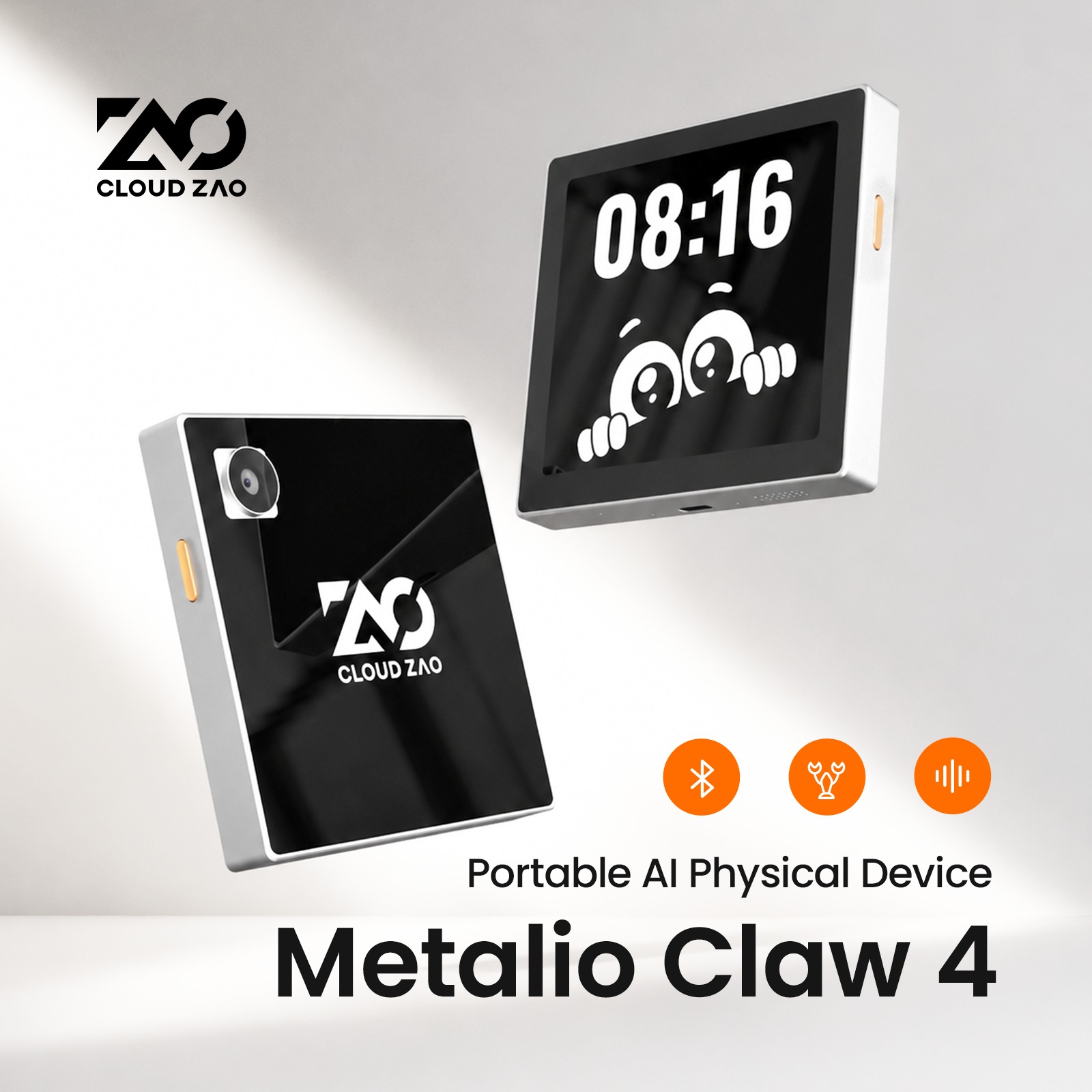
一款 8×8cm 掌上开源便携 AI 设备,基于 ESP32-P4 双核架构集成摄像头、GPS、4G 与无线充电,通过 OpenClaw 云端 Agent 实现语音交互与自动功能生成。
Stars: 25 | Forks: 14
# Metalio Claw4
720x720 LVGL 9 Touch UI · Voice Wake-up · Power Key PWR_KEY"] apps["Application Layer
Chat · Radio · Recording · OpenClaw · Camera · GPS · Weather · Music · Digital Human · ..."] svc["Service Layer
AudioService · GpsService · SdCardManager · MCP Server"] proto["Protocol Layer
WebSocket · MQTT+UDP · OpenClaw HTTP API"] board["Board Abstraction
DualNetworkBoard · Display · AudioCodec · Backlight · Gauge"] drv["Driver Layer
MIPI-DSI · MIPI-CSI · I2S · SDMMC · I2C · UART · IOExpander"] subgraph hw["Hardware"] direction LR p4["ESP32-P4 Host
Main MCU · UI · Audio/Video · Camera"] c5["ESP32-C5 Slave
Wi-Fi SDIO"] nt26["NT26 4G
Cellular"] end cloud["OpenClaw Cloud
ASR · LLM · TTS · Agent Orchestration"] ui --> apps --> svc --> proto --> board --> drv --> hw proto <--> cloud ### 4.1 Data Flow (Voice Dialogue) flowchart LR speak["User speaks"] --> mic["I2S microphone"] mic --> sr["ESP-SR wake-word / VAD"] sr --> enc["AudioService encodes"] enc --> link["WebSocket / MQTT"] link --> asr["Cloud ASR"] asr --> llm["LLM"] llm --> tts["TTS"] tts --> rx["Device receives audio stream"] rx --> spk["I2S speaker playback"] rx --> lvgl["LVGL UI updates
chat bubbles / chat emotion EAF / digital-human expressions"] ## 5. Hardware Specifications | Category | Spec | |:--------------- |:------------------------------------------------------------------------------------------------------------------------------------------------------ | | **Size** | Approx. 8×8 cm (palm‑size) | | **Main MCU** | ESP32‑P4, dual‑core RISC‑V 480 MHz; Flash 32 MB, PSRAM 32 MB | | **Storage** | On‑board 32 MB Flash (partition table see `partitions/`) + microSD slot | | **Display** | 3.95‑inch square MIPI‑DSI, 720×720, 24 bpp | | **Touch** | GT911 capacitive touch (I2C) | | **Audio** | Professional Bluetooth audio codec (replaces ES8311 + ES7210); I2S microphone/speaker 16 kHz; doubles as codec / Bluetooth speaker / Bluetooth headset | | **Camera** | OV2710, MIPI‑CSI, 2 MP (1920×1080 @ 25 fps), 24 MHz XCLK | | **Positioning** | GPS module (UART NMEA‑0183, 9600 baud) | | **Sensors** | | | **Network** | 2.4 / 5 GHz Wi‑Fi (ESP32‑C5) + 4G LTE (NT26); ships with embedded 4G SIM‑patch, supports external SIM | | **Bluetooth** | Professional Bluetooth audio codec (UART 115200, AT commands); see [§12.1](#121-bluetooth-audio-and-three-modes) | | **Power** | Single‑cell Li‑ion + BQ27220 fuel gauge | | **Charging** | Wired USB + Qi wireless (see [NU1680](#nu1680-charging-current-control)) | | **Vibration** | Vibration motor (GPIO 22, LEDC PWM) | | **Button** | Power key (`PWR_KEY` / `PWR_KEY_PULSE` via IO extender; see [Power‑IC & Power Key](#power-ic-and-power-key)) | ## 6. Dual‑Chip Architecture Metalio Claw4 uses an **ESP32‑P4 + ESP32‑C5** heterogeneous dual‑chip design, communicating via Espressif’s **ESP‑Hosted** framework: flowchart TB p4["ESP32-P4 Host
LVGL UI · Audio/Video · Camera · GPS / Sensors"] c5["ESP32-C5 Slave
Wi-Fi STA/AP · Network Stack"] nt26["NT26 4G Module
LTE Cellular"] p4 <-->|"SDIO 4-bit
CMD=50 CLK=51 D0=49
D1=34 D2=31 D3=53
RESET=54"| c5 p4 -->|"UART
TX=28 RX=29 MRDY=13 SRDY=4"| nt26 | Chip | Role | Interface | Responsibility | |:------------ |:----------------- |:---------------- |:---------------------------------------------------------------- | | **ESP32‑P4** | Host MCU | — | UI, audio/video, camera, GPS, SD card, protocols, OpenClaw / MCP | | **ESP32‑C5** | Slave Coprocessor | SDIO Slot 1 | 2.4 / 5 GHz Wi‑Fi connection, network stack (via ESP‑Hosted RPC) | | **NT26** | Cellular Module | UART + MRDY/SRDY | 4G LTE data, switchable with Wi‑Fi | ## 7. Peripherals and Pins Pin definitions source: `main/boards/metalio-claw-4/config.h` IO extender mapping source: `main/boards/common/IOExpander.hpp` P4 ↔ C5 SDIO pins: defined in `sdkconfig` via `CONFIG_ESP_HOSTED_SDIO_*` (P4 host side configurable; C5 slave side fixed by IOMUX). ### 7.1 ESP32‑P4 Direct GPIOs | Function | GPIO | Note | |:------------------- |:-----:|:---------------------------------------------------- | | I2C SDA | 7 | Shared bus: GT911, TCA9555, BQ27220, QMC6309, NU1680 | | I2C SCL | 8 | | | I2S Mic WS | 10 | Audio input | | I2S Mic DIN | 11 | | | I2S Speaker BCLK | 12 | Audio output | | I2S Speaker DOUT | 9 | | | NT26 SRDY | 4 | 4G module flow‑control | | NT26 MRDY | 13 | 4G module flow‑control | | NT26 TX → Module RX | 28 | UART | | NT26 RX ← Module TX | 29 | UART | | Camera XCLK | 32 | 24 MHz clock output | | GPS TX → Module RX | 38 | UART0 | | GPS RX ← Module TX | 37 | UART0 | | Boot Button | 35 | | | BT Audio TX | 26 | UART2, 115200 | | BT Audio RX | 27 | | | LCD Reset | 3 | Shared reset line with camera | | Backlight PWM | 52 | | | SDMMC CLK | 43 | 4‑bit SD card | | SDMMC CMD | 44 | | | SDMMC D0‑D3 | 39‑42 | | | Vibration Motor | 22 | LEDC PWM control | ### 7.2 ESP‑Hosted SDIO (P4 ↔ C5) Metalio Claw4 connects P4 and C5 via **SDIO Slot 1**, 4‑bit bus at **40 MHz** clock. P4 host‑side pins are configured in `sdkconfig`; C5 slave‑side pins are fixed by the chip’s IOMUX and cannot be changed in software. | Signal | ESP32‑P4 GPIO (Host) | ESP32‑C5 GPIO (Slave) | Note | |:------ |:--------------------:|:---------------------:|:----------------------------------------------------- | | CMD | 50 | 10 | | | CLK | 51 | 9 | | | D0 | 49 | 8 | | | D1 | 34 | 7 | | | D2 | 31 | 14 | | | D3 | 53 | 13 | | | RESET | 54 | RST/EN | P4 output, **active‑high**; each P4 startup resets C5 | | Parameter | Value | `sdkconfig` Item | |:--------------- |:----------- |:--------------------------------------------- | | SDIO Slot | Slot 1 | `CONFIG_ESP_HOSTED_SDIO_SLOT_1` | | Bus Width | 4‑bit | `CONFIG_ESP_HOSTED_SDIO_4_BIT_BUS` | | Clock Frequency | 40 MHz | `CONFIG_ESP_HOSTED_SDIO_CLOCK_FREQ_KHZ=40000` | | Reset Polarity | High‑active | `CONFIG_ESP_HOSTED_SDIO_RESET_ACTIVE_HIGH` | ### 7.3 TCA9555 IO Expander (I2C 16‑bit) | Logical Pin | Hardware Line | Direction | Function | |:------------------- |:-------------:|:---------:|:------------------------------------------------ | | GPS_POWER | P0‑0 | OUT | GPS module power (**high‑enable**) | | PA_SWITCH | P0‑1 | OUT | Audio amp source switch (low = 4G, high = Wi‑Fi) | | CAM_PWDN | P0‑2 | OUT | Camera power (**low‑enable**) | | SD | P0‑3 | OUT | SD card power (**low‑enable**) | | PWR_KEY_PULSE | P0‑4 | OUT | Pulse to power‑IC for software shutdown | | PWR_KEY | P0‑5 | IN | Side power‑key | | BT_POWER | P0‑6 | OUT | Bluetooth module power (**high‑enable**) | | RST_4G | P0‑7 | OUT | 4G module power (**high‑enable**) | | PA | P1‑0 | OUT | Audio amplifier enable (**high‑enable**) | | ACCEL_INT | P1‑1 | IN | Accelerometer interrupt | | USB_INSERT_DET | P1‑2 | IN | USB plug‑in detection | | WIRELESS_CHARGE_DET | P1‑3 | IN | Wireless charging detection | ### 7.4 I2C Device Addresses | Device | 7‑bit Address | Note | |:----------------------- |:-------------:|:------------------------------------------------------------------------------ | | GT911 Touch | 0x5D / 0x14 | Auto‑detected | | TCA9555 IO Expander | 0x20 | 16‑bit | | BQ27220 Fuel Gauge | 0x55 | Single‑cell Li‑ion | | NU1680 Wireless Charger | 0x60 | Qi receiver; see [`NU1680 charging current`](#nu1680-charging-current-control) | | QMC6309 Magnetometer | 0x7C | Three‑axis | | OV2710 Camera SCCB | 0x36 | MIPI‑CSI | ### 7.5 Peripheral Block Diagram flowchart LR subgraph p4["ESP32-P4"] direction TB i2cBus["I2C GPIO 7/8"] i2s["I2S GPIO 9/10/11/12"] dsi["MIPI-DSI"] csi["MIPI-CSI"] sdmmc["SDMMC 4-bit"] uart0["UART0"] uart2["UART2"] uart4g["UART + MRDY/SRDY"] sdio["SDIO Host"] end mic["I2S Mic"] --> i2s i2s --> spk["I2S Spk"] dsi --> lcd["720x720 LCD"] dsi --> touch["GT911 Touch"] i2cBus --> tca["TCA9555"] i2cBus --> bq["BQ27220"] i2cBus --> nu["NU1680"] i2cBus --> qmc["QMC6309"] tca --> gpsPwr["GPS power"] tca --> camPwr["CAM power"] tca --> btPwr["BT power"] tca --> pwr4g["4G power"] tca --> sdPa["SD / PA"] csi <--> ov["OV2710 Camera"] sdmmc <--> sd["microSD"] uart0 <--> gps["GPS Module"] uart2 <--> bt["BT Audio Module"] uart4g <--> nt26["NT26 4G"] sdio <--> c5["ESP32-C5 Wi-Fi"] ## 8. Schematic Explanation *(The original document left this section blank; keep it as‑is.)* ## 9. Software Architecture Metalio Claw4 firmware is based on the [XiaoZhi AI (xiaozhi-esp32)](https://github.com/78/xiaozhi-esp32) framework, customized for the `metalio-claw-4` board. ### 9.1 Layered Structure | Layer | Directory / Module | Responsibility | |:------------------ |:------------------------- |:----------------------------------------------- | | **Entry** | `main.cc` → `Application` | Startup, event loop, state machine | | **Board** | `boards/metalio-claw-4/` | Hardware init, pin mux | | **Display** | `display/screen/*` | LVGL 9 app pages | | **Audio** | `audio/` | Codec, wake‑word, AEC | | **Protocol** | `protocols/` | WebSocket, MQTT+UDP | | **MCP** | `mcp_server.cc` | Device‑side Model Context Protocol | | **UI i18n** | `main/i18n/` | Runtime zh‑CN / en‑US (`catalog.json` → `I18n::T`); Settings **Language** tab, NVS‑persisted | | **Common Drivers** | `boards/common/` | GPS, SD card, fuel gauge, IO expander, dual‑net, virtual USB (`usb_virtual_disk`) | ### 9.2 State Machine `Application` tracks device state: stateDiagram-v2 [*] --> starting starting --> configuring configuring --> idle idle --> connecting connecting --> idle connecting --> listening listening --> speaking speaking --> listening speaking --> idle idle --> upgrading idle --> activating connecting --> fatal_error upgrading --> idle activating --> idle - **idle** – waiting for wake‑word - **listening** – recording, streaming ASR upstream - **speaking** – playing TTS response - **connecting** – establishing WebSocket / MQTT link ### 9.3 Board Initialization Order In `metalio-claw-4.cc` constructor: flowchart TD s1["1. I2C bus GPIO 7/8"] --> s2["2. TCA9555 IO expander
power peripherals; PA after ~8s; CAM/SD default off"] s2 --> s3["3. BQ27220 fuel gauge + low-voltage protection"] s3 --> s4["4. Bluetooth audio UART + default mode 1"] s4 --> s5["5. SD mount + virtual USB worker
USB Serial/JTAG by default"] s5 --> s6["6. MIPI-DSI LCD"] s6 --> s7["7. GT911 touch"] s7 --> s8["8. LVGL display adapter"] s8 --> s9["9. NU1680 wireless-charge detect task"] s9 --> s10["10. System monitor CPU / RAM / battery"] s10 --> s11["11. I18n::Init read NVS locale
after NVS ready in main.cc"] ### 9.4 Project Layout main/ ├── application.cc # Startup, state machine, protocol routing ├── i18n/ # Runtime UI locales (catalog.json) ├── boards/metalio-claw-4/ # Metalio Claw4 board init │ ├── config.h # GPIO pins, screen params │ ├── config.json # Build config │ └── metalio-claw-4.cc # Board entry point ├── display/screen/ # LVGL apps (incl. settings / standby / test / sd_card) ├── audio/ # Capture, playback, wake‑word ├── protocols/ # WebSocket / MQTT └── boards/common/ # Common drivers (GPS, SD, fuel gauge, usb_virtual_disk, …) esp_claw_bin/ # ESPClaw (ota_1) companion images & flash notes partitions/v1/32m_dual.csv # 32 MB dual-system table (ota_0=main FW, ota_1=ESPClaw) ## 10. OpenClaw OpenClaw is Metalio’s cloud AI Agent platform. The device talks to it through HTTP API: | API | Path | Purpose | |:----------------- |:------------------------------------------ |:------------------------------ | | Device Status | `GET /api/v1/devices/status` | Report / query device state | | Conversation List | `GET /api/v1/conversation?page=1&size=100` | Fetch historical sessions | | Message Log | `GET /api/v1/conversation/{id}/messages` | Get messages of a conversation | | Clear Sessions | `POST /api/v1/conversation/removeAll` | Delete all conversations | API base defined in `main/api_endpoints.h`. The device‑side **OpenClaw App** (`openclaw_screen`) provides: - Hold‑to‑talk to send voice commands - Message‑bubble chat UI - Multi‑turn dialogue with the cloud Agent ### 10.1 ESPClaw (Local Dual‑Boot) Unlike cloud **OpenClaw**, the home‑screen **ESPClaw** entry boots the local edge_agent flashed in **`ota_1`** (emote / system / storage partitions are also required): | Slot | Partition table | Contents | |:---|:---|:---| | `ota_0` (~9 M @ `0x200000`) | `partitions/v1/32m_dual.csv` | This repo’s main firmware (xingzhi / MetalioClaw4) | | `ota_1` (~4 M) | same | ESPClaw `edge_agent` | | `emote` / `system` / `storage` | same | ESPClaw emote assets & FAT storage | - Tap home **ESPClaw** → after confirm, switch boot partition to `ota_1` and reboot - If ESPClaw images were never flashed, the UI reports ESPClaw not found - **Flash guide & full image list**: [`esp_claw_bin/README.md`](esp_claw_bin/README.md); partition‑table offset must be `CONFIG_PARTITION_TABLE_OFFSET=0x9000` ## 11. Built‑in Applications Home‑screen app list (`home_screen.cc` → `kApps[]`): | App | ID | Description | |:-------------- |:---------------- |:------------------------------------------------------------------------ | | Chat | `chat` | XiaoZhi AI voice chat; **text bubbles** or **EAF emotion** view (§11.1) | | Network Config | `wifi` | Wi‑Fi / 4G switch, SIM swap (internal / external) | | Digital Human | `digital_people` | SD‑card SJPG expression animation | | Phone | `call` | 4G calls (**external SIM only**) | | Music | `music` | Bluetooth speaker mode (BT mode 3), phone‑push lyric display | | Calendar | `calendar` | Calendar view | | OpenClaw | `openclaw` | Cloud Agent dialogue (§10) | | ESPClaw | `espclaw` | Switch to `ota_1` local edge_agent (§10.1) | | Camera | `camera` | OV2710 preview & capture (1920×1080) | | Location | `gps` | GPS / Wi‑Fi / Base‑station positioning (latter two need 4G mode) | | Spirit Level | `spirit_level` | Tilt angle | | Magnet | `magnet` | QMC6309 three‑axis visualization | | Vibrate | `vibrate` | Vibration motor test (GPIO 22) | | Calculator | `calculator` | Four‑function arithmetic | | Weather | `weather` | City weather query | | SD Card | `sd` | Browse / delete files; **Enable virtual USB** (§14.6) | | Pin Test | `pin` | GPIO test | | 2048 | `2048` | Small game | | System Info | `info` | Firmware version / chip / MAC | | Theme | `theme` | Four icon‑theme packs | | Test | `test` | Factory entry: auto test, stress test, hardware tests, etc. | | Settings | `settings` | Volume / brightness / standby / **language (zh/en)** / Bluetooth modes | | Radio | `radio` | Internet HLS radio + spectrum visualizer (§11.2) | | Recording | `recording` | SD Opus record / list playback / cloud ASR (§11.3) | #### Settings - **Language**: Runtime switch Simplified Chinese / English (`I18n::SetLocale`, NVS); home rebuilds after change - **Standby**: Configure “enter standby” and “cumulative shutdown” (minutes; 0 = disable) - **Bluetooth**: Former standalone Bluetooth Config lives here (modes 1/2/3, scan & pair, Reset Bluetooth) - Volume and backlight are also here (no separate home **Backlight** icon) #### Test Factory / stress entry (`test_screen`): auto tests (fuel gauge / wireless charge / camera, …), stress test (LVGL + BGM + motor + camera loop), hardware checks. Everyday users can ignore this. #### 11.1 Chat (`chat`) - Header toggles **Chat** / **Emotion** modes - **Chat mode**: left/right text bubbles (assistant/system left, user right) - **Emotion mode**: plays SD‑card EAF animations at `/sdcard/system/chat/{emotion}.eaf` (server emotion name; must match `[A-Za-z0-9_-]`); one shared white caption at the bottom shows the latest message - Requires the SD card and files under that directory; emotion mode is unavailable without them #### 11.2 Radio (`radio`) - Network **HLS (m3u8)** live streams; built‑in station table (`radio_stations.h`) - Spectrum visualization while playing; entering the page pauses the system voice path and restores wake‑word on exit - **Prefer Wi‑Fi**; 4G uses a lot of data (UI shows a warning) #### 11.3 Recording (`recording`) - **Requires SD card**: if unmounted, only a hint is shown - **Record** tab: start / stop with timer; saves **Ogg Opus** to `/sdcard/recordings/REC_*.opus` (much smaller than PCM WAV) - **List** tab: lists `.opus` (legacy `.wav` still supported); tap opens a **detail** page (does not play immediately) - **Detail**: play / stop; **Transcribe** uploads the file as multipart to `POST /api/v1/asr/transcribe` (`X-Device-Id`) and shows full text, duration, dialogue lines, and summary - API base paths live in `main/api_endpoints.h` (`kAsrTranscribe`) ## 12. Communication Protocols | Protocol | Use | |:----------------- |:-------------------------------------- | | **WebSocket** | Real‑time voice dialogue (ASR/LLM/TTS) | | **MQTT + UDP** | Alternate cloud uplink | | **MCP** | Expose device abilities to LLM | | **OpenClaw HTTP** | Cloud Agent API | | **Bluetooth AT** | Bluetooth audio module control | ### 12.1 Bluetooth Audio & Three Modes ESP32‑P4 talks to the Bluetooth codec via **UART** (115200, GPIO 26/27) using AT commands to switch work modes; hardware overview see [§2.4](#professional-bluetooth-audio-solution). Bluetooth UART and `BT_POWER` pin appear in [§7.1](#71-esp32-p4-direct-gpio) and [§7.3](#73-tca9555-io-expander-i2c-16-bit). #### Mode Overview Think of the Bluetooth chip’s three modes as three tasks: **(1) everyday XiaoZhi chat**, **(2) talk via Bluetooth ear‑/speaker**, **(3) use phone as remote to play music**. Most switches are handled automatically by firmware. **Mode 1 – Daily XiaoZhi Chat (boot default)** Device powers up in mode 1, the default for normal voice interaction. The Bluetooth codec routes I2S for XiaoZhi’s mic & speaker; you just wake‑word → chat. Exiting the **Music** app automatically returns to mode 1. **Mode 2 – External Bluetooth Device for XiaoZhi Chat** To chat via a Bluetooth headset or speaker (must have a mic), open **Settings → Bluetooth**, select **Mode 2**, scan, pair. Audio routes to the paired device. Return to mode 1 by manually switching back on the same tab. **Mode 3 – Phone → Device as Bluetooth Speaker** Open the **Music** app → firmware auto‑switches to mode 3 (speaker‑waiting). Connect phone via Bluetooth, play music from any app; song info and (if supported) lyrics appear on screen. Leaving the Music app restores mode 1 automatically. | Mode | One‑line Summary | How to Enter | How to Exit | |:----------:|:------------------------------------------- |:----------------------------------- |:-------------------------------------- | | **Mode 1** | Normal XiaoZhi talk; default on boot | Boot auto; exit Music → auto‑return | Usually stay in default | | **Mode 2** | Use Bluetooth ear‑/speaker for XiaoZhi talk | **Settings → Bluetooth** → Mode 2 | Manual switch back to Mode 1 | | **Mode 3** | Phone uses device as Bluetooth speaker | Open Music app (auto‑switch) | Exit Music app (auto‑return to Mode 1) | #### Mode‑Switch AT Commands Switching requires a preceding `AT+RX` / `AT+TX` then a ~700 ms delay before `AT+MODE`. Firmware handles the delay in a background task. | Target Mode | Send Order (each ends with `\r\n`) | Note | |:----------- |:---------------------------------- |:------------------------------------- | | **Mode 1** | `AT+RX=2` → 700 ms → `AT+MODE=1` | Normal XiaoZhi chat; power‑on default | | **Mode 2** | `AT+TX=1` → 700 ms → `AT+MODE=2` | TX / pairing mode | | **Mode 3** | `AT+RX=1` → 700 ms → `AT+MODE=3` | Music‑receiver (speaker) mode | Successful switch replies with `SET MODE 1` / `SET MODE 2` / `SET MODE 3`. **Automatic Switch Triggers (firmware behavior)** | Trigger | Sent Commands | |:------------------------------------------- |:---------------------------------------- | | Device power‑on | `AT+RX=2` → `AT+MODE=1` (Mode 1) | | Enter **Music** page | `AT+RX=1` → `AT+MODE=3` (Mode 3) | | Leave **Music** page | `AT+RX=2` → `AT+MODE=1` (back to Mode 1) | | Bluetooth Settings tab – mode button pressed | Follow table above for selected mode | #### Mode 2: Scan & Connect After switching to Mode 2 in **Settings → Bluetooth**, you can use these AT commands (the remote device **must have a mic** for voice chat). | Action | AT Command | Note | |:-------------------------- |:-------------------------- |:-------------------------------------------------------------------- | | Scan nearby devices | `AT+INQUIRING` | Replies `INQUIRING START`; device lines: `AT+BT:<12‑hex‑addr>` |
| Connect to specific device | `AT+CONNECT=<12‑hex‑addr>` | Example: `AT+CONNECT=AABBCCDDEEFF` |
| Scan end | — | Module replies `INQ COMPLETE` |
| Connect success | — | Module replies `CONNECT SUCCESS` |
| Connect timeout | — | Module replies `CONNECT TIMEOUT` |
After a successful link, Mode 2 panel lets you toggle audio profile:
| Action | AT Sequence | Note |
|:--------------------- |:------------------------ |:------------------------ |
| Voice call (SCO) | `AT+PP=1` → `AT+BTSCO=1` | Build SCO for telephony |
| Music playback (A2DP) | `AT+BTSCO=0` → `AT+PP=1` | Drop SCO, revert to A2DP |
#### Mode 3: Music‑Page Controls
Entering the **Music** page auto‑sets Mode 3; the screen shows song title & scrolling lyrics (3‑line). Buttons map to AT commands:
| Action | AT Command |
|:------------------- |:------------- |
| Previous track | `AT+PREV` |
| Next track | `AT+NEXT` |
| Play | `AT+MPLAY=1` |
| Pause | `AT+MPAUSE=1` |
| Volume up | `AT+VOLUP` |
| Volume down | `AT+VOLDOWN` |
| Play/Pause (toggle) | `AT+PP` |
#### Bluetooth Reset (Maintenance)
**Settings → Bluetooth → Reset Bluetooth** pulls low/high on `BT_POWER` via the IO extender, power‑cycling the Bluetooth module into download mode. Use **only** when flashing Bluetooth firmware; normal operation does not need it. See [§14.5](#145-bluetooth-chip-flashing).
## 13. Development Environment
### 13.1 Requirements
| Item | Requirement |
|:------------------- |:------------------------------------------------------------- |
| **ESP‑IDF** | **v5.5.4** (must match repository `sdkconfig`) |
| **Target** | ESP32‑P4 (pre‑configured; no need to run `idf.py set-target`) |
| **Board** | Metalio Claw4 (`main/boards/metalio-claw-4/`) |
| **OS** | Linux / macOS / Windows (WSL2 recommended) |
| **Python** | 3.8+ (ESP‑IDF provides a venv) |
| **USB‑UART Driver** | CH340 / CP2102 etc., according to debug interface |
### 13.2 Installing ESP‑IDF
**Official docs (recommended first read):**
[ESP32‑P4 Getting Started — ESP‑IDF v5.5.4](https://docs.espressif.com/projects/esp-idf/zh_CN/v5.5.4/esp32p4/get-started/index.html)
Linux/macOS quick install:
git clone -b v5.5.4 --recursive https://github.com/espressif/esp-idf.git
cd esp-idf
./install.sh esp32p4
. ./export.sh
Windows: follow the official [Windows toolchain guide](https://docs.espressif.com/projects/esp-idf/zh_CN/v5.5.4/esp32p4/get-started/windows-setup.html) or use WSL2 with the Linux steps.
**Verify installation:**
idf.py --version
### 13.3 Obtaining Firmware Source
git clone https://github.com/CloudZao/MetalioClaw4.git
cd MetalioClaw4
The repo ships with a ready‑to‑use `sdkconfig`; after cloning you can run `idf.py build` directly—no `idf.py set-target` needed. See [§14.2](#142-about-sdkconfig) for `sdkconfig` notes.
### 13.4 Key Configuration
| Config Item | Value | Comment |
|:------------- |:----------------- |:----------------------------- |
| ESP‑IDF | v5.5.4 | Must match |
| Target | esp32p4 | Pre‑set |
| ESP‑Hosted | SDIO → ESP32‑C5 | Wi‑Fi coprocessor |
| Device AEC | Enabled | Full‑duplex echo cancellation |
| Screen Driver | NV3051F (default) | FL7707N optional |
## 14. Compilation and Flashing
### 14.1 Build
# Ensure ESP‑IDF environment is sourced
. ~/esp-idf/export.sh # adjust path as needed
# Direct build; no set‑target required
idf.py build
Output artifacts appear in the `build/` directory.
### 14.2 About sdkconfig
**Do not edit `sdkconfig` casually.** It is already tuned for Metalio Claw4 hardware (ESP‑Hosted SDIO Wi‑Fi coprocessor, MIPI‑DSI display, PSRAM, etc.). Arbitrary changes may break boot, display, Wi‑Fi/4G, camera, or SD‑card init.
If customization is needed, prefer adding overrides via `sdkconfig.defaults` or the board‑level `config.json` field `sdkconfig_append`.
### 14.3 USB Debug Ports
When plugged in and powered, the device typically presents **four** serial ports. Port names (e.g., `COM3`, `/dev/ttyUSB0`) may vary; identify them by their **descriptors**:
| Purpose | System Descriptor | Note |
|:-------------------------------------------- |:---------------------------- |:------------------------------------------------------------------------------------------------- |
| **ESP32‑P4** main‑controller flashing / logs | `USB JTAG/serial debug unit` | Use for `idf.py flash monitor` (P4 firmware). **Note:** while **virtual USB** is enabled in the SD Card app, the same pins (GPIO24/25) switch to MSC — this port is unavailable until virtual USB is disabled or you leave the SD page |
| **Bluetooth codec** comms / flashing | `USB Serial` (`CH340K`) | Independent USB UART; use for Bluetooth‑chip flashing (see [§14.5](#145-bluetooth-chip-flashing)) |
| **4G module** runtime log | `log` | View NT26 output |
| **4G module** AT‑command debugging | `at` | Send AT commands directly; baud‑rate per modem spec |
### 14.4 ESP32‑P4 Flash & Monitor
Replace `/dev/ttyACM0` with the port showing descriptor **“USB JTAG/serial debug unit”**.
# Flash + live log
idf.py -p /dev/ttyACM0 flash monitor
| Platform | How to Spot the P4 Port |
|:-------- |:---------------------------------------------------------------- |
| Windows | Device Manager → port description **USB JTAG/serial debug unit** |
| Linux | `ls /dev/ttyACM*` or `dmesg` → look for JTAG/Serial device |
| macOS | `/dev/cu.usbmodem*` etc.; use the descriptor shown by the system |
`monitor` opens a serial log; quit with `Ctrl+]`.
**Flash‑only:**
idf.py -p /dev/ttyACM0 flash
**Log‑only:**
idf.py -p /dev/ttyACM0 monitor
### 14.5 Bluetooth‑Chip Flashing
The Bluetooth audio codec has its own USB‑UART (CH340K). Flashing must use that port, **not** the P4 JTAG port.
**Steps:**
1. Plug in USB, power the device. Locate the port whose descriptor is **`USB Serial` (CH340K)**.
2. Open your Bluetooth‑flash tool and select that CH340K port.
3. Put the Bluetooth module into download mode:
- From the home screen, open **Settings → Bluetooth** and tap **Reset Bluetooth**; **or** power‑cycle the device.
- The module will enter download mode, ready for flashing.
- If the flash tool cannot see the device, repeat step 3 then retry.
4. After flashing, again tap **Reset Bluetooth** or power‑cycle to boot with the new firmware.
### 14.6 SD‑Card Resources & Virtual USB Drive
Assets for features like the Digital Human are in the [`sd_images/`](sd_images/) folder. Copy the contents to the root of a FAT‑formatted SD card, preserving the directory structure. Details are in [sd_images/README.md](sd_images/README.md).
Common paths:
| Path | Purpose |
|:---|:---|
| `/sdcard/system/emotion/` | Digital‑human SJPG emotions |
| `/sdcard/system/chat/` | Chat emotion‑mode `.eaf` (`{emotion}.eaf`) |
| `/sdcard/recordings/` | Recording app Opus files (and legacy WAV) |
#### Virtual USB Drive (USB MSC)
The device can expose microSD as **USB Mass Storage** to a PC (`usb_virtual_disk`, TinyUSB MSC):
1. Confirm the SD card is inserted and the **SD Card** app shows it mounted.
2. Open **SD Card** → tap **Enable virtual USB**.
3. After the PC mounts the drive, copy files; **the same USB port is no longer Serial/JTAG** — stop flashing/monitoring first.
4. **Eject / safely remove** on the PC, then tap **Disable virtual USB**; or leave the SD Card page (auto force‑disable and best‑effort restore of serial).
### 14.7 ESPClaw Dual‑System Flashing
Before using home **ESPClaw**, Flash must follow `partitions/v1/32m_dual.csv` and include edge_agent / emote / system / storage images from `esp_claw_bin/`.
**Recommended:** flash the main firmware and ESPClaw‑related bins in **one full pass**. Naming convention and `esptool` examples:
- [`esp_claw_bin/README.md`](esp_claw_bin/README.md)
Partition‑table offset must be **`0x9000`** (same as edge_agent).
## 15. Debugging and Common Issues
### 15.1 Log Tags
| Tag | Module |
|:---------------- |:--------------------------------- |
| `METALIO_CLAW_4` | Board initialization |
| `IOExpander` | TCA9555 IO expander |
| `GpsService` | GPS NMEA parsing |
| `CameraScreen` | Camera preview |
| `OpenClawScreen` | OpenClaw dialogue |
| `ChatScreen` | Chat / emotion mode |
| `RadioScreen` | Internet radio |
| `RecordingScreen`| Recording / ASR transcription |
| `System Monitor` | CPU / RAM / battery periodic logs |
### 15.2 System Monitor
After board init, a background task prints CPU usage, free memory, and battery status each second—handy for performance/power analysis.
### 15.3 Pin Test & Factory Test
- Home **Pin Test**: quick GPIO / peripheral connectivity check (`pin_test_screen`).
- Home **Test**: factory entry (auto test, stress test, hardware tests, … — `test_screen`).
### 15.4 Frequently Asked Questions
**Q: Compilation complains about ESP‑IDF version mismatch**
A: Make sure you are using **ESP‑IDF v5.5.4** and have sourced the environment (`./export.sh`) before each build.
**Q: Screen stays dark**
A: 1. Verify `sdkconfig` has not been edited accidentally. 2. Check MIPI‑DSI LDO supply (channel 3, 2500 mV). 3. Confirm screen driver: default `NV3051F`; alternate `FL7707N` via `METALIO_CLAW_4_USE_FL7707N` macro.
**Q: Wi‑Fi not scanning**
A: Metalio Claw4 gets Wi‑Fi via ESP‑Hosted SDIO to the ESP32‑C5 coprocessor. If the C5 firmware isn’t flashed or the SDIO link is faulty, Wi‑Fi won’t work. Refer to the [Dual‑Chip Architecture](#6-dual-chip-architecture) and [Peripherals and Pins](#7-peripherals-and-pins) sections to verify wiring and firmware.
**Q: 4G fails to register**
A: 1. Ensure you switched to **4G mode** in the **Network Configuration** app. 2. Confirm the internal 4G patch SIM or external SIM is active and not overdue. 3. For external SIM, check it is properly inserted. 4. Watch the NT26 module’s `AT+CEREG` status in the serial log.
**Q: Phone app can’t dial**
A: The internal SIM supports data only. Insert an external SIM, switch to it in **Network Configuration**, then use the **Phone** app. See [§2.4 4G & SIM Card](#4g-and-sim-card).
**Q: Wi‑Fi / base‑station positioning unavailable**
A: These require the device to be in **4G network mode** with the module successfully registered. Refer to [§2.4 4G‑Assisted Positioning](#4g-assisted-positioning-location-app).
**Q: SD‑card mount fails**
A: 1. Check the SD card is FAT32 formatted. 2. Verify external power to the SD‑card slot: the IO extender pin `SD` (P0‑3) must be low to enable; firmware drives it low on boot. 3. Ensure the SDMMC PHY power domain is enabled (see `config.h` `SDMMC_LDO_CHAN_ID`, default LDO chan 4); `SdCardManager` requests it at mount time. 4. If the log shows `Failed to create SD power control driver`, the power domain isn’t ready. 5. Confirm SDMMC pins match `config.h`.
**Q: Home screen enters standby / powers off after a few minutes idle**
A: Expected behavior – configurable under **Settings → Standby**; see [§2.5 Power & Battery Life](#25-power-and-battery-life).
**Q: Screen suddenly turns blue (blue‑screen)**
A: A blue screen indicates a firmware crash; the device auto‑reboots. After reboot you should see the animation and return to the home screen. If blue‑screens recur, connect the serial log to inspect the crash details, ensure you are running the latest firmware, and if the issue persists, file an issue.
*This document tracks firmware revisions. Should you notice any mismatch between the descriptions here and the actual hardware, please submit an Issue.*
720x720 LVGL 9 Touch UI · Voice Wake-up · Power Key PWR_KEY"] apps["Application Layer
Chat · Radio · Recording · OpenClaw · Camera · GPS · Weather · Music · Digital Human · ..."] svc["Service Layer
AudioService · GpsService · SdCardManager · MCP Server"] proto["Protocol Layer
WebSocket · MQTT+UDP · OpenClaw HTTP API"] board["Board Abstraction
DualNetworkBoard · Display · AudioCodec · Backlight · Gauge"] drv["Driver Layer
MIPI-DSI · MIPI-CSI · I2S · SDMMC · I2C · UART · IOExpander"] subgraph hw["Hardware"] direction LR p4["ESP32-P4 Host
Main MCU · UI · Audio/Video · Camera"] c5["ESP32-C5 Slave
Wi-Fi SDIO"] nt26["NT26 4G
Cellular"] end cloud["OpenClaw Cloud
ASR · LLM · TTS · Agent Orchestration"] ui --> apps --> svc --> proto --> board --> drv --> hw proto <--> cloud ### 4.1 Data Flow (Voice Dialogue) flowchart LR speak["User speaks"] --> mic["I2S microphone"] mic --> sr["ESP-SR wake-word / VAD"] sr --> enc["AudioService encodes"] enc --> link["WebSocket / MQTT"] link --> asr["Cloud ASR"] asr --> llm["LLM"] llm --> tts["TTS"] tts --> rx["Device receives audio stream"] rx --> spk["I2S speaker playback"] rx --> lvgl["LVGL UI updates
chat bubbles / chat emotion EAF / digital-human expressions"] ## 5. Hardware Specifications | Category | Spec | |:--------------- |:------------------------------------------------------------------------------------------------------------------------------------------------------ | | **Size** | Approx. 8×8 cm (palm‑size) | | **Main MCU** | ESP32‑P4, dual‑core RISC‑V 480 MHz; Flash 32 MB, PSRAM 32 MB | | **Storage** | On‑board 32 MB Flash (partition table see `partitions/`) + microSD slot | | **Display** | 3.95‑inch square MIPI‑DSI, 720×720, 24 bpp | | **Touch** | GT911 capacitive touch (I2C) | | **Audio** | Professional Bluetooth audio codec (replaces ES8311 + ES7210); I2S microphone/speaker 16 kHz; doubles as codec / Bluetooth speaker / Bluetooth headset | | **Camera** | OV2710, MIPI‑CSI, 2 MP (1920×1080 @ 25 fps), 24 MHz XCLK | | **Positioning** | GPS module (UART NMEA‑0183, 9600 baud) | | **Sensors** | | | **Network** | 2.4 / 5 GHz Wi‑Fi (ESP32‑C5) + 4G LTE (NT26); ships with embedded 4G SIM‑patch, supports external SIM | | **Bluetooth** | Professional Bluetooth audio codec (UART 115200, AT commands); see [§12.1](#121-bluetooth-audio-and-three-modes) | | **Power** | Single‑cell Li‑ion + BQ27220 fuel gauge | | **Charging** | Wired USB + Qi wireless (see [NU1680](#nu1680-charging-current-control)) | | **Vibration** | Vibration motor (GPIO 22, LEDC PWM) | | **Button** | Power key (`PWR_KEY` / `PWR_KEY_PULSE` via IO extender; see [Power‑IC & Power Key](#power-ic-and-power-key)) | ## 6. Dual‑Chip Architecture Metalio Claw4 uses an **ESP32‑P4 + ESP32‑C5** heterogeneous dual‑chip design, communicating via Espressif’s **ESP‑Hosted** framework: flowchart TB p4["ESP32-P4 Host
LVGL UI · Audio/Video · Camera · GPS / Sensors"] c5["ESP32-C5 Slave
Wi-Fi STA/AP · Network Stack"] nt26["NT26 4G Module
LTE Cellular"] p4 <-->|"SDIO 4-bit
CMD=50 CLK=51 D0=49
D1=34 D2=31 D3=53
RESET=54"| c5 p4 -->|"UART
TX=28 RX=29 MRDY=13 SRDY=4"| nt26 | Chip | Role | Interface | Responsibility | |:------------ |:----------------- |:---------------- |:---------------------------------------------------------------- | | **ESP32‑P4** | Host MCU | — | UI, audio/video, camera, GPS, SD card, protocols, OpenClaw / MCP | | **ESP32‑C5** | Slave Coprocessor | SDIO Slot 1 | 2.4 / 5 GHz Wi‑Fi connection, network stack (via ESP‑Hosted RPC) | | **NT26** | Cellular Module | UART + MRDY/SRDY | 4G LTE data, switchable with Wi‑Fi | ## 7. Peripherals and Pins Pin definitions source: `main/boards/metalio-claw-4/config.h` IO extender mapping source: `main/boards/common/IOExpander.hpp` P4 ↔ C5 SDIO pins: defined in `sdkconfig` via `CONFIG_ESP_HOSTED_SDIO_*` (P4 host side configurable; C5 slave side fixed by IOMUX). ### 7.1 ESP32‑P4 Direct GPIOs | Function | GPIO | Note | |:------------------- |:-----:|:---------------------------------------------------- | | I2C SDA | 7 | Shared bus: GT911, TCA9555, BQ27220, QMC6309, NU1680 | | I2C SCL | 8 | | | I2S Mic WS | 10 | Audio input | | I2S Mic DIN | 11 | | | I2S Speaker BCLK | 12 | Audio output | | I2S Speaker DOUT | 9 | | | NT26 SRDY | 4 | 4G module flow‑control | | NT26 MRDY | 13 | 4G module flow‑control | | NT26 TX → Module RX | 28 | UART | | NT26 RX ← Module TX | 29 | UART | | Camera XCLK | 32 | 24 MHz clock output | | GPS TX → Module RX | 38 | UART0 | | GPS RX ← Module TX | 37 | UART0 | | Boot Button | 35 | | | BT Audio TX | 26 | UART2, 115200 | | BT Audio RX | 27 | | | LCD Reset | 3 | Shared reset line with camera | | Backlight PWM | 52 | | | SDMMC CLK | 43 | 4‑bit SD card | | SDMMC CMD | 44 | | | SDMMC D0‑D3 | 39‑42 | | | Vibration Motor | 22 | LEDC PWM control | ### 7.2 ESP‑Hosted SDIO (P4 ↔ C5) Metalio Claw4 connects P4 and C5 via **SDIO Slot 1**, 4‑bit bus at **40 MHz** clock. P4 host‑side pins are configured in `sdkconfig`; C5 slave‑side pins are fixed by the chip’s IOMUX and cannot be changed in software. | Signal | ESP32‑P4 GPIO (Host) | ESP32‑C5 GPIO (Slave) | Note | |:------ |:--------------------:|:---------------------:|:----------------------------------------------------- | | CMD | 50 | 10 | | | CLK | 51 | 9 | | | D0 | 49 | 8 | | | D1 | 34 | 7 | | | D2 | 31 | 14 | | | D3 | 53 | 13 | | | RESET | 54 | RST/EN | P4 output, **active‑high**; each P4 startup resets C5 | | Parameter | Value | `sdkconfig` Item | |:--------------- |:----------- |:--------------------------------------------- | | SDIO Slot | Slot 1 | `CONFIG_ESP_HOSTED_SDIO_SLOT_1` | | Bus Width | 4‑bit | `CONFIG_ESP_HOSTED_SDIO_4_BIT_BUS` | | Clock Frequency | 40 MHz | `CONFIG_ESP_HOSTED_SDIO_CLOCK_FREQ_KHZ=40000` | | Reset Polarity | High‑active | `CONFIG_ESP_HOSTED_SDIO_RESET_ACTIVE_HIGH` | ### 7.3 TCA9555 IO Expander (I2C 16‑bit) | Logical Pin | Hardware Line | Direction | Function | |:------------------- |:-------------:|:---------:|:------------------------------------------------ | | GPS_POWER | P0‑0 | OUT | GPS module power (**high‑enable**) | | PA_SWITCH | P0‑1 | OUT | Audio amp source switch (low = 4G, high = Wi‑Fi) | | CAM_PWDN | P0‑2 | OUT | Camera power (**low‑enable**) | | SD | P0‑3 | OUT | SD card power (**low‑enable**) | | PWR_KEY_PULSE | P0‑4 | OUT | Pulse to power‑IC for software shutdown | | PWR_KEY | P0‑5 | IN | Side power‑key | | BT_POWER | P0‑6 | OUT | Bluetooth module power (**high‑enable**) | | RST_4G | P0‑7 | OUT | 4G module power (**high‑enable**) | | PA | P1‑0 | OUT | Audio amplifier enable (**high‑enable**) | | ACCEL_INT | P1‑1 | IN | Accelerometer interrupt | | USB_INSERT_DET | P1‑2 | IN | USB plug‑in detection | | WIRELESS_CHARGE_DET | P1‑3 | IN | Wireless charging detection | ### 7.4 I2C Device Addresses | Device | 7‑bit Address | Note | |:----------------------- |:-------------:|:------------------------------------------------------------------------------ | | GT911 Touch | 0x5D / 0x14 | Auto‑detected | | TCA9555 IO Expander | 0x20 | 16‑bit | | BQ27220 Fuel Gauge | 0x55 | Single‑cell Li‑ion | | NU1680 Wireless Charger | 0x60 | Qi receiver; see [`NU1680 charging current`](#nu1680-charging-current-control) | | QMC6309 Magnetometer | 0x7C | Three‑axis | | OV2710 Camera SCCB | 0x36 | MIPI‑CSI | ### 7.5 Peripheral Block Diagram flowchart LR subgraph p4["ESP32-P4"] direction TB i2cBus["I2C GPIO 7/8"] i2s["I2S GPIO 9/10/11/12"] dsi["MIPI-DSI"] csi["MIPI-CSI"] sdmmc["SDMMC 4-bit"] uart0["UART0"] uart2["UART2"] uart4g["UART + MRDY/SRDY"] sdio["SDIO Host"] end mic["I2S Mic"] --> i2s i2s --> spk["I2S Spk"] dsi --> lcd["720x720 LCD"] dsi --> touch["GT911 Touch"] i2cBus --> tca["TCA9555"] i2cBus --> bq["BQ27220"] i2cBus --> nu["NU1680"] i2cBus --> qmc["QMC6309"] tca --> gpsPwr["GPS power"] tca --> camPwr["CAM power"] tca --> btPwr["BT power"] tca --> pwr4g["4G power"] tca --> sdPa["SD / PA"] csi <--> ov["OV2710 Camera"] sdmmc <--> sd["microSD"] uart0 <--> gps["GPS Module"] uart2 <--> bt["BT Audio Module"] uart4g <--> nt26["NT26 4G"] sdio <--> c5["ESP32-C5 Wi-Fi"] ## 8. Schematic Explanation *(The original document left this section blank; keep it as‑is.)* ## 9. Software Architecture Metalio Claw4 firmware is based on the [XiaoZhi AI (xiaozhi-esp32)](https://github.com/78/xiaozhi-esp32) framework, customized for the `metalio-claw-4` board. ### 9.1 Layered Structure | Layer | Directory / Module | Responsibility | |:------------------ |:------------------------- |:----------------------------------------------- | | **Entry** | `main.cc` → `Application` | Startup, event loop, state machine | | **Board** | `boards/metalio-claw-4/` | Hardware init, pin mux | | **Display** | `display/screen/*` | LVGL 9 app pages | | **Audio** | `audio/` | Codec, wake‑word, AEC | | **Protocol** | `protocols/` | WebSocket, MQTT+UDP | | **MCP** | `mcp_server.cc` | Device‑side Model Context Protocol | | **UI i18n** | `main/i18n/` | Runtime zh‑CN / en‑US (`catalog.json` → `I18n::T`); Settings **Language** tab, NVS‑persisted | | **Common Drivers** | `boards/common/` | GPS, SD card, fuel gauge, IO expander, dual‑net, virtual USB (`usb_virtual_disk`) | ### 9.2 State Machine `Application` tracks device state: stateDiagram-v2 [*] --> starting starting --> configuring configuring --> idle idle --> connecting connecting --> idle connecting --> listening listening --> speaking speaking --> listening speaking --> idle idle --> upgrading idle --> activating connecting --> fatal_error upgrading --> idle activating --> idle - **idle** – waiting for wake‑word - **listening** – recording, streaming ASR upstream - **speaking** – playing TTS response - **connecting** – establishing WebSocket / MQTT link ### 9.3 Board Initialization Order In `metalio-claw-4.cc` constructor: flowchart TD s1["1. I2C bus GPIO 7/8"] --> s2["2. TCA9555 IO expander
power peripherals; PA after ~8s; CAM/SD default off"] s2 --> s3["3. BQ27220 fuel gauge + low-voltage protection"] s3 --> s4["4. Bluetooth audio UART + default mode 1"] s4 --> s5["5. SD mount + virtual USB worker
USB Serial/JTAG by default"] s5 --> s6["6. MIPI-DSI LCD"] s6 --> s7["7. GT911 touch"] s7 --> s8["8. LVGL display adapter"] s8 --> s9["9. NU1680 wireless-charge detect task"] s9 --> s10["10. System monitor CPU / RAM / battery"] s10 --> s11["11. I18n::Init read NVS locale
after NVS ready in main.cc"] ### 9.4 Project Layout main/ ├── application.cc # Startup, state machine, protocol routing ├── i18n/ # Runtime UI locales (catalog.json) ├── boards/metalio-claw-4/ # Metalio Claw4 board init │ ├── config.h # GPIO pins, screen params │ ├── config.json # Build config │ └── metalio-claw-4.cc # Board entry point ├── display/screen/ # LVGL apps (incl. settings / standby / test / sd_card) ├── audio/ # Capture, playback, wake‑word ├── protocols/ # WebSocket / MQTT └── boards/common/ # Common drivers (GPS, SD, fuel gauge, usb_virtual_disk, …) esp_claw_bin/ # ESPClaw (ota_1) companion images & flash notes partitions/v1/32m_dual.csv # 32 MB dual-system table (ota_0=main FW, ota_1=ESPClaw) ## 10. OpenClaw OpenClaw is Metalio’s cloud AI Agent platform. The device talks to it through HTTP API: | API | Path | Purpose | |:----------------- |:------------------------------------------ |:------------------------------ | | Device Status | `GET /api/v1/devices/status` | Report / query device state | | Conversation List | `GET /api/v1/conversation?page=1&size=100` | Fetch historical sessions | | Message Log | `GET /api/v1/conversation/{id}/messages` | Get messages of a conversation | | Clear Sessions | `POST /api/v1/conversation/removeAll` | Delete all conversations | API base defined in `main/api_endpoints.h`. The device‑side **OpenClaw App** (`openclaw_screen`) provides: - Hold‑to‑talk to send voice commands - Message‑bubble chat UI - Multi‑turn dialogue with the cloud Agent ### 10.1 ESPClaw (Local Dual‑Boot) Unlike cloud **OpenClaw**, the home‑screen **ESPClaw** entry boots the local edge_agent flashed in **`ota_1`** (emote / system / storage partitions are also required): | Slot | Partition table | Contents | |:---|:---|:---| | `ota_0` (~9 M @ `0x200000`) | `partitions/v1/32m_dual.csv` | This repo’s main firmware (xingzhi / MetalioClaw4) | | `ota_1` (~4 M) | same | ESPClaw `edge_agent` | | `emote` / `system` / `storage` | same | ESPClaw emote assets & FAT storage | - Tap home **ESPClaw** → after confirm, switch boot partition to `ota_1` and reboot - If ESPClaw images were never flashed, the UI reports ESPClaw not found - **Flash guide & full image list**: [`esp_claw_bin/README.md`](esp_claw_bin/README.md); partition‑table offset must be `CONFIG_PARTITION_TABLE_OFFSET=0x9000` ## 11. Built‑in Applications Home‑screen app list (`home_screen.cc` → `kApps[]`): | App | ID | Description | |:-------------- |:---------------- |:------------------------------------------------------------------------ | | Chat | `chat` | XiaoZhi AI voice chat; **text bubbles** or **EAF emotion** view (§11.1) | | Network Config | `wifi` | Wi‑Fi / 4G switch, SIM swap (internal / external) | | Digital Human | `digital_people` | SD‑card SJPG expression animation | | Phone | `call` | 4G calls (**external SIM only**) | | Music | `music` | Bluetooth speaker mode (BT mode 3), phone‑push lyric display | | Calendar | `calendar` | Calendar view | | OpenClaw | `openclaw` | Cloud Agent dialogue (§10) | | ESPClaw | `espclaw` | Switch to `ota_1` local edge_agent (§10.1) | | Camera | `camera` | OV2710 preview & capture (1920×1080) | | Location | `gps` | GPS / Wi‑Fi / Base‑station positioning (latter two need 4G mode) | | Spirit Level | `spirit_level` | Tilt angle | | Magnet | `magnet` | QMC6309 three‑axis visualization | | Vibrate | `vibrate` | Vibration motor test (GPIO 22) | | Calculator | `calculator` | Four‑function arithmetic | | Weather | `weather` | City weather query | | SD Card | `sd` | Browse / delete files; **Enable virtual USB** (§14.6) | | Pin Test | `pin` | GPIO test | | 2048 | `2048` | Small game | | System Info | `info` | Firmware version / chip / MAC | | Theme | `theme` | Four icon‑theme packs | | Test | `test` | Factory entry: auto test, stress test, hardware tests, etc. | | Settings | `settings` | Volume / brightness / standby / **language (zh/en)** / Bluetooth modes | | Radio | `radio` | Internet HLS radio + spectrum visualizer (§11.2) | | Recording | `recording` | SD Opus record / list playback / cloud ASR (§11.3) | #### Settings - **Language**: Runtime switch Simplified Chinese / English (`I18n::SetLocale`, NVS); home rebuilds after change - **Standby**: Configure “enter standby” and “cumulative shutdown” (minutes; 0 = disable) - **Bluetooth**: Former standalone Bluetooth Config lives here (modes 1/2/3, scan & pair, Reset Bluetooth) - Volume and backlight are also here (no separate home **Backlight** icon) #### Test Factory / stress entry (`test_screen`): auto tests (fuel gauge / wireless charge / camera, …), stress test (LVGL + BGM + motor + camera loop), hardware checks. Everyday users can ignore this. #### 11.1 Chat (`chat`) - Header toggles **Chat** / **Emotion** modes - **Chat mode**: left/right text bubbles (assistant/system left, user right) - **Emotion mode**: plays SD‑card EAF animations at `/sdcard/system/chat/{emotion}.eaf` (server emotion name; must match `[A-Za-z0-9_-]`); one shared white caption at the bottom shows the latest message - Requires the SD card and files under that directory; emotion mode is unavailable without them #### 11.2 Radio (`radio`) - Network **HLS (m3u8)** live streams; built‑in station table (`radio_stations.h`) - Spectrum visualization while playing; entering the page pauses the system voice path and restores wake‑word on exit - **Prefer Wi‑Fi**; 4G uses a lot of data (UI shows a warning) #### 11.3 Recording (`recording`) - **Requires SD card**: if unmounted, only a hint is shown - **Record** tab: start / stop with timer; saves **Ogg Opus** to `/sdcard/recordings/REC_*.opus` (much smaller than PCM WAV) - **List** tab: lists `.opus` (legacy `.wav` still supported); tap opens a **detail** page (does not play immediately) - **Detail**: play / stop; **Transcribe** uploads the file as multipart to `POST /api/v1/asr/transcribe` (`X-Device-Id`) and shows full text, duration, dialogue lines, and summary - API base paths live in `main/api_endpoints.h` (`kAsrTranscribe`) ## 12. Communication Protocols | Protocol | Use | |:----------------- |:-------------------------------------- | | **WebSocket** | Real‑time voice dialogue (ASR/LLM/TTS) | | **MQTT + UDP** | Alternate cloud uplink | | **MCP** | Expose device abilities to LLM | | **OpenClaw HTTP** | Cloud Agent API | | **Bluetooth AT** | Bluetooth audio module control | ### 12.1 Bluetooth Audio & Three Modes ESP32‑P4 talks to the Bluetooth codec via **UART** (115200, GPIO 26/27) using AT commands to switch work modes; hardware overview see [§2.4](#professional-bluetooth-audio-solution). Bluetooth UART and `BT_POWER` pin appear in [§7.1](#71-esp32-p4-direct-gpio) and [§7.3](#73-tca9555-io-expander-i2c-16-bit). #### Mode Overview Think of the Bluetooth chip’s three modes as three tasks: **(1) everyday XiaoZhi chat**, **(2) talk via Bluetooth ear‑/speaker**, **(3) use phone as remote to play music**. Most switches are handled automatically by firmware. **Mode 1 – Daily XiaoZhi Chat (boot default)** Device powers up in mode 1, the default for normal voice interaction. The Bluetooth codec routes I2S for XiaoZhi’s mic & speaker; you just wake‑word → chat. Exiting the **Music** app automatically returns to mode 1. **Mode 2 – External Bluetooth Device for XiaoZhi Chat** To chat via a Bluetooth headset or speaker (must have a mic), open **Settings → Bluetooth**, select **Mode 2**, scan, pair. Audio routes to the paired device. Return to mode 1 by manually switching back on the same tab. **Mode 3 – Phone → Device as Bluetooth Speaker** Open the **Music** app → firmware auto‑switches to mode 3 (speaker‑waiting). Connect phone via Bluetooth, play music from any app; song info and (if supported) lyrics appear on screen. Leaving the Music app restores mode 1 automatically. | Mode | One‑line Summary | How to Enter | How to Exit | |:----------:|:------------------------------------------- |:----------------------------------- |:-------------------------------------- | | **Mode 1** | Normal XiaoZhi talk; default on boot | Boot auto; exit Music → auto‑return | Usually stay in default | | **Mode 2** | Use Bluetooth ear‑/speaker for XiaoZhi talk | **Settings → Bluetooth** → Mode 2 | Manual switch back to Mode 1 | | **Mode 3** | Phone uses device as Bluetooth speaker | Open Music app (auto‑switch) | Exit Music app (auto‑return to Mode 1) | #### Mode‑Switch AT Commands Switching requires a preceding `AT+RX` / `AT+TX` then a ~700 ms delay before `AT+MODE`. Firmware handles the delay in a background task. | Target Mode | Send Order (each ends with `\r\n`) | Note | |:----------- |:---------------------------------- |:------------------------------------- | | **Mode 1** | `AT+RX=2` → 700 ms → `AT+MODE=1` | Normal XiaoZhi chat; power‑on default | | **Mode 2** | `AT+TX=1` → 700 ms → `AT+MODE=2` | TX / pairing mode | | **Mode 3** | `AT+RX=1` → 700 ms → `AT+MODE=3` | Music‑receiver (speaker) mode | Successful switch replies with `SET MODE 1` / `SET MODE 2` / `SET MODE 3`. **Automatic Switch Triggers (firmware behavior)** | Trigger | Sent Commands | |:------------------------------------------- |:---------------------------------------- | | Device power‑on | `AT+RX=2` → `AT+MODE=1` (Mode 1) | | Enter **Music** page | `AT+RX=1` → `AT+MODE=3` (Mode 3) | | Leave **Music** page | `AT+RX=2` → `AT+MODE=1` (back to Mode 1) | | Bluetooth Settings tab – mode button pressed | Follow table above for selected mode | #### Mode 2: Scan & Connect After switching to Mode 2 in **Settings → Bluetooth**, you can use these AT commands (the remote device **must have a mic** for voice chat). | Action | AT Command | Note | |:-------------------------- |:-------------------------- |:-------------------------------------------------------------------- | | Scan nearby devices | `AT+INQUIRING` | Replies `INQUIRING START`; device lines: `AT+BT:<12‑hex‑addr>
标签:ESP32, UML, 人工智能, 嵌入式系统, 开源硬件, 智能设备, 物联网, 用户模式Hook绕过, 语音交互